Background Information:
A network of shallow (generally less than 10 feet deep) soil monitoring wells
have been installed on various soil types, geologic deposits, and landforms in
Southeastern Massachusetts (Plymouth and Bristol Counties). The wells are used
to monitor seasonal water table fluctuations to assist town Boards of Health and
Health Agents guide onsite wastewater disposal system location, design, and
permitting. The wells also provide important soil data such as depth to seasonal
high water table and period of time the water table exists. This data is then
provided in
published in County Soil Survey Reports. This program is joint effort between
the USDA-Natural Resources Conservation Service, Massachusetts Coastal Zone
Management, the Buzzards Bay Project, and local towns.
History: The monitoring wells were first installed in the Buzzards Bay Watershed
beginning as early as 1991. Over 60 wells have been installed in the Watershed,
some of the wells are still being monitored periodically, others were destroyed
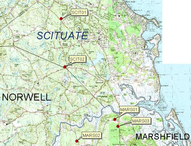
or access to them denied. In 2001 a network of wells is currently being
installed in the upper portion of the South Coastal Watershed, as of January
2001, 5 wells have been installed in Scituate and Marshfield. Plans are to
install several more wells in the area.
Installation Procedure: Site selection for the monitoring wells were chosen based on a series of
factors such as access to the property, ease of access for recording the data,
hydrologic conditions, soil and geology type, and landscape setting. Once an
appropriate site is selected a small hand-dug test pit is dug and a log of the
test pit is recorded following standard USDA-NRCS soil morphology description
procedure. Logs of the test pits are used to determine soil properties such as
permeability, depth to redox morphology, soil parent material (surficial
geology), and soil classification. The pits are dug to a depth of 65 inches or
as deep as possible with the equipment used during the installation. After the
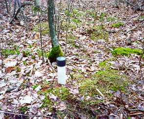
pit is dug and described, a mechanical drill is used to core as deep as possible
for the well. A 2 inch screened PVC well is then installed following the
procedure outlined in the
WRP Technical Note HY-IA-3.1 Installing Monitoring
Wells/Piezometers in Wetlands, August 1993 (email to receive a copy). The pits
are then filled back in with the soil material and sealed with bentonite clay.
Monitoring the Wells: After installation, the wells are checked on a regular basis and the depth
to water is recorded for each well. The frequency of readings varies from time
of year. During the summer months when the wells are dry, they are often just
checked once a month unless a rain event occurs. If water is detected
observation frequency is increased. During the spring and fall as water tables
rise, the wells are checked bi-monthly. On some of the wells data on soil and
air temperature is also recorded along with climate history and vegetation
observation (budding condition, leaf fall off, etc.). Soil temperature is
recorded using a temperature probe installed at a depth of 20 inches (50 cm),
this depth is used for soil classification (temperature regime). Soil temperature is very
important to determine when the growing season starts and microbial activity
starts and ends. The critical soil temperature for microbial activity is called
biological zero, this is when the soil temperature at 20 inches is at or below
41F (5C). Below this temperature the soil is considered dormant for soil
morphologic development of redoximorphic features. This is very important because the
soil monitoring wells will often show water tables higher than the depth to redox
features identified in the soil test pit. This high water table is not recorded in the soil
because it often occurs during the winter months when the soil is below
biological zero. Redoximorphic formation requires the soil to be above
biological zero and saturated for a period of time (typically two weeks during
the growing season). For more information on soil temperature and growing
seasons click HERE.
The data from the wells is recorded in a spread sheet along with other data
collected. The spread sheet data will be made available for each well along with
graphs and statistical data.
How to Use this Monitoring Well Data: The intended use of this data is to assist town health agents better effectively
guide on-site wastewater disposal system location, design, and permitting. A
major component of this process is proper soil evaluation for the estimated
average depth of seasonal high water table. This depth is determined by the
guidelines described in Title V (310 CMR, section 15.103-3) by a licensed soil
evaluator. The index wells will help in the determination of the start and end
of the wet season and provide a reference to compare proposed systems on similar
soil and landscape positions. An example of the use of these wells is the
situation which occurred during the early winter of 2002, a time of extreme
drought conditions and record dry conditions. Readings made during early
January, a time when water tables should have been at or near their highest, had
most of the wells completely dry. January 2002 was not the start of the wet
season.
The Title V code requires that reference materials of the site of the
proposed new system be included with the soil log. The soil survey map is one of
the required reference materials on the form (NOTE: when working in Plymouth
County check to see if updated soil mapping is available, go to
http://nesoil.com/plymouth for more
information. The updated mapping will be more accurate for on-site septic system
limitations than the old 1969 survey). The index wells are referenced by soil
type (Woodbridge series for example), landscape setting (e.g. convex slope of a
drumlin), location by town, and geologic deposit (e.g. glacial till). Below is a
table with each wells information and a map showing the distribution of the
wells. To use the data try to select a well that best matches the site
conditions of the site of the proposed system (match soil type, geology,
landscape, and nearest location) and click on the well to go to its data site.